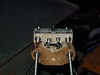
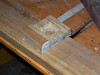
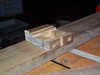
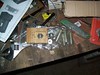
A4983 Carrier

Stepper Driver
Here's one of my new stepper controllers. They can't put more than 0.5A into my 1.68 ohm motors from the 12v supply without overheating, probably due to current squared losses in the chips' fets. I will have to try a lower voltage. The white stuff is some heatsink compound- I was trying to heatsink the chip with little success. I will try something with a clip that goes under the board to hold it steady.

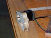
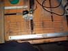
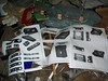
Quadrature Wheel

Ball Mouse Belly

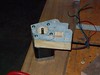
Buffer

Being Used as Input
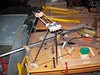
I'm using a gutted ball mouse as an input device. I'm picking the quadrature signals directly off the photodiodes, so they need some buffering. Quadrature translates perfectly to step/dir, so this allows precise bidirectional control of my stepper. With the A4983 set to 16x microstepping, I have 3200 steps per rev and therefore a wicked reduction ratio from the mouses' wheel. I'm re-splining my stepper shaft because the other splines weren't close enough to the motor body, and I already had this rig set up to test the drivers with. The arduino is in this circuit for two reasons: 1) to count pulses and tell me where I'm up to, and 2) to debounce the pulses, and provide them at a steady rate to my stepper controller to avoid missed steps and noise getting into it.

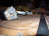
Overview

Re-Splined Shaft